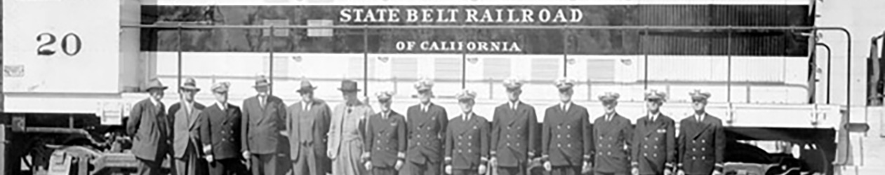
I’ve had several people ask “what am I doing” and “how big is this layout”. I’m building the State Belt Railway of California, which served parts of the waterfront of San Francisco, mainly the parts in the “older” parts of town (there were extensive docks & shipyards further south, served by the SP, SF or the WP, but I’m not worried about those).
The State Belt was owned & operated by the Port Commission of California, and served all of the industries and piers in the area, switching cars on an as-needed & as-directed basis by each of the connecting railroads. This allowed railroads other than the dreaded Octopus (the Southern Pacific railroad) to serve the city.
Most of the railroad was within a block or two of the waterfront, running on The Embarcadero. One section that went further afield was along North Point & Beach streets. It’s two or three blocks from the water (ooh, so far away!). It should be going uphill such that by the time the line reaches Del Monte, the street is on the 2nd level of the building, while on the opposite side the street is at the 1st level. That couldn’t happen in the shortened distance that I have available to me.
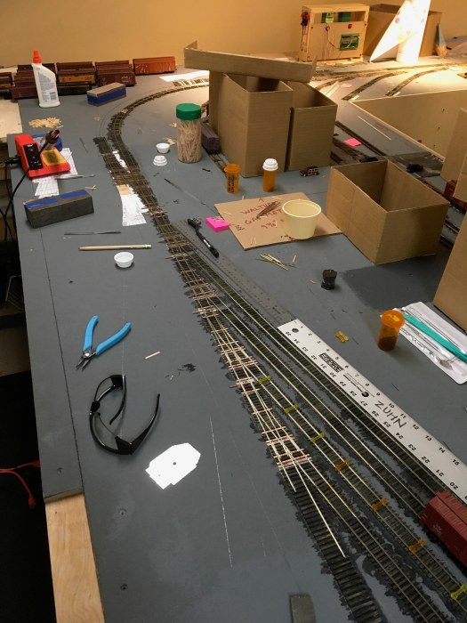
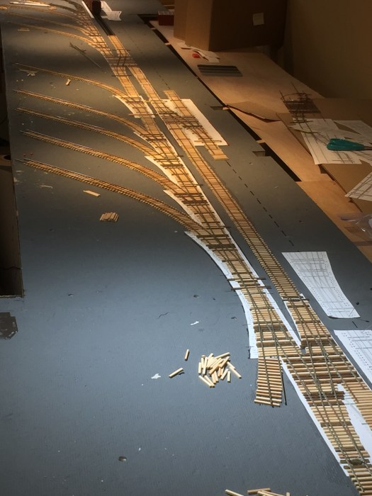
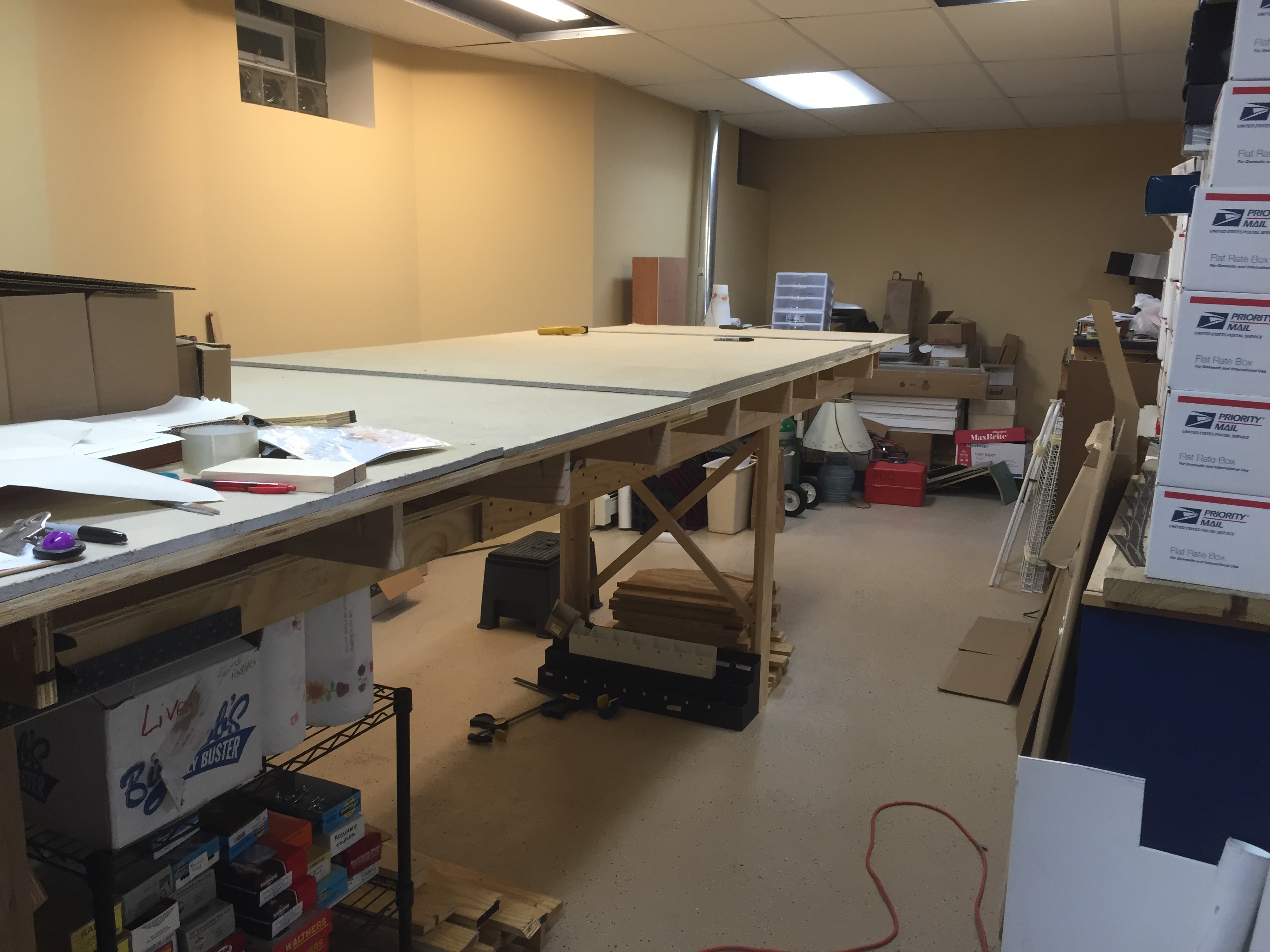
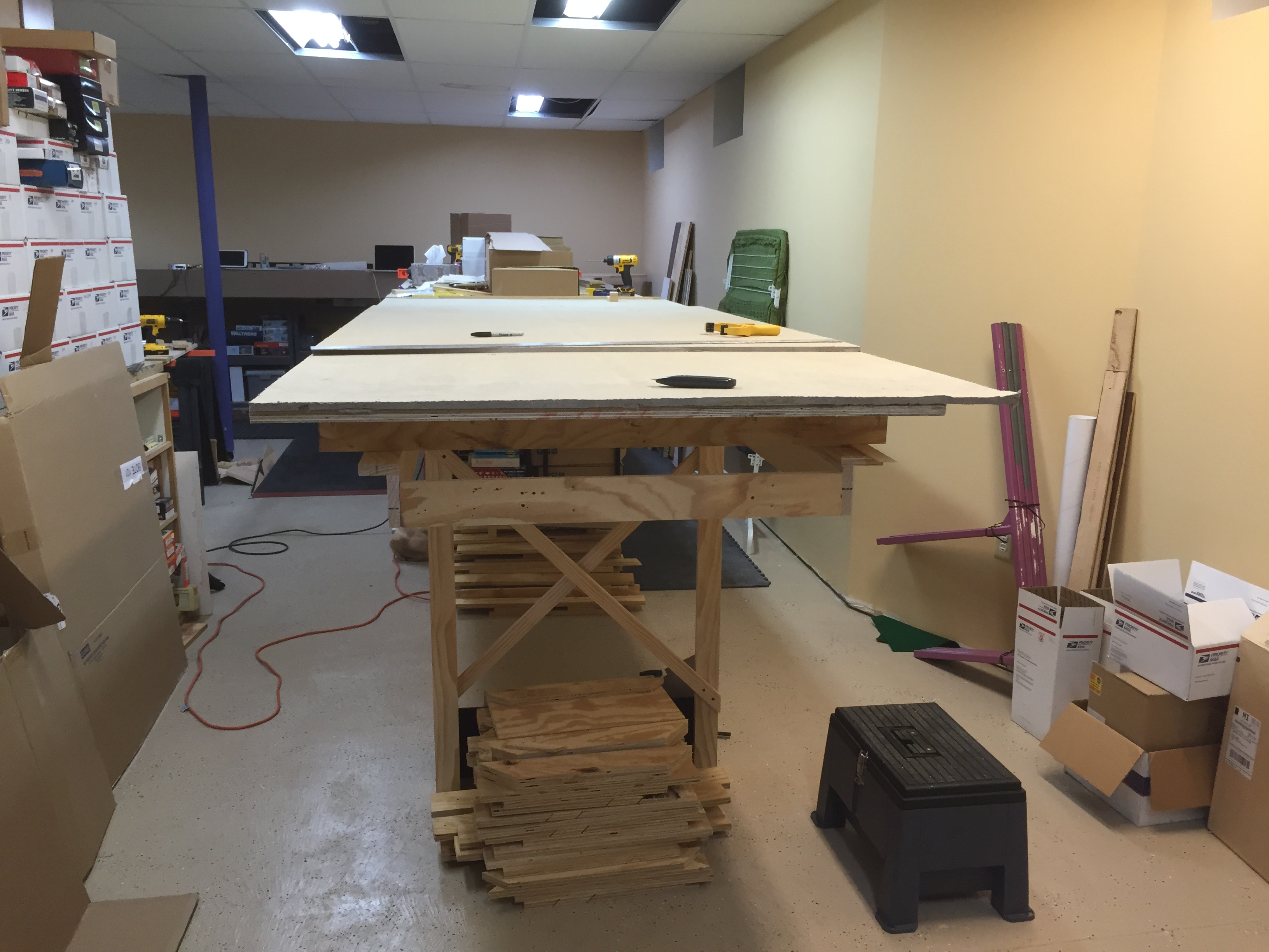
So what is that space? I’ve got U-shaped benchwork, with the base against a wall and aisles alongside both legs of the U. One leg is about 16′ long, and the other about 24′. All work so far is either on this 16′ section, or on the base. Work is underway, hence tools & other cruft on the benchwork, but this gives you an idea of what is happening.
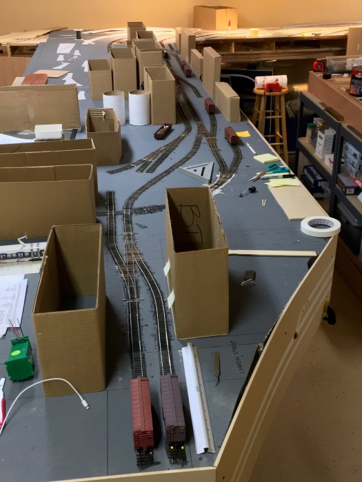
The track is all handlaid. Switches are mostly #5 built using the FastTracks jig, but with one curved switch built completely “by hand”. The double crossing (with slight curve) was built by Dave Vos. Switches are thrown using pushbuttons on the fascia, which control Tortoise motors via an Arduino based system. This lets me use momentary switches to control the tortoise (which usually wants a latching SPDT or DPDT control). There’s also a light in the pushbutton, which is lit for reverse, off for normal, and (soon) flashing while the motor is in motion.
There are a few places where a switch will need to be conveniently thrown from multiple locations (one side or the other of the benchwork), and this will let me pull that off.
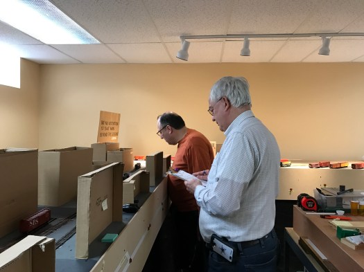
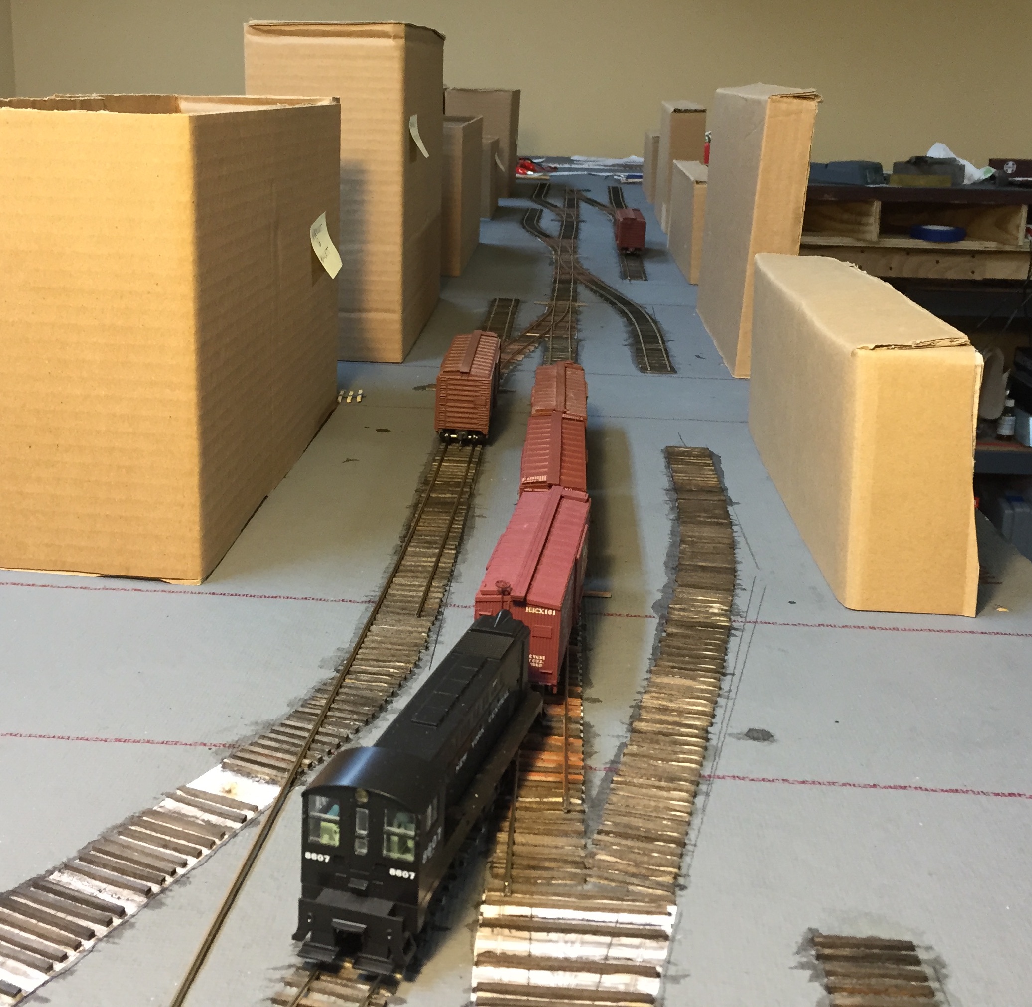
Building mockups give me a vague idea of what this will look like. The buildings aren’t too tall on this side of town, and most of these mockups are a bit too tall. But it’s still enough to make the train look fairly small as it moves on the street trackage (pretty much everything you see here is embedded in pavement).
Here’s the updated version of my prototype map, showing what was there (at some point or another — I doubt that all of these existed at the same moment in time). What I’ve built is close. Certainly within the realm of “feels right to me”.
Just about all of these industries unloaded to the sidewalk or a truck. None of these tracks had a traditional loading platform. That’s common throughout the State Belt. The actual industry may be several blocks away, but they’ll truck the load to their building. The block marked in black on the map below had tracks running to it (it was a malting operation), but I just couldn’t find a way to get those into my plan.

I expect that this area will be operated by a two person crew. There are no run-arounds on this section at all, so there needs to be some supporting trackage on the Embarcadero to make this operable. Most of that street has two or three parallel tracks alongside the roadway (see http://www.snowcrest.net/photobob/sb11.html for a photo).
I’ll be posting more about the next section shortly.