Switch Motors Ready For Use…

Switch motors ready for use...
Switch motors ready for use…

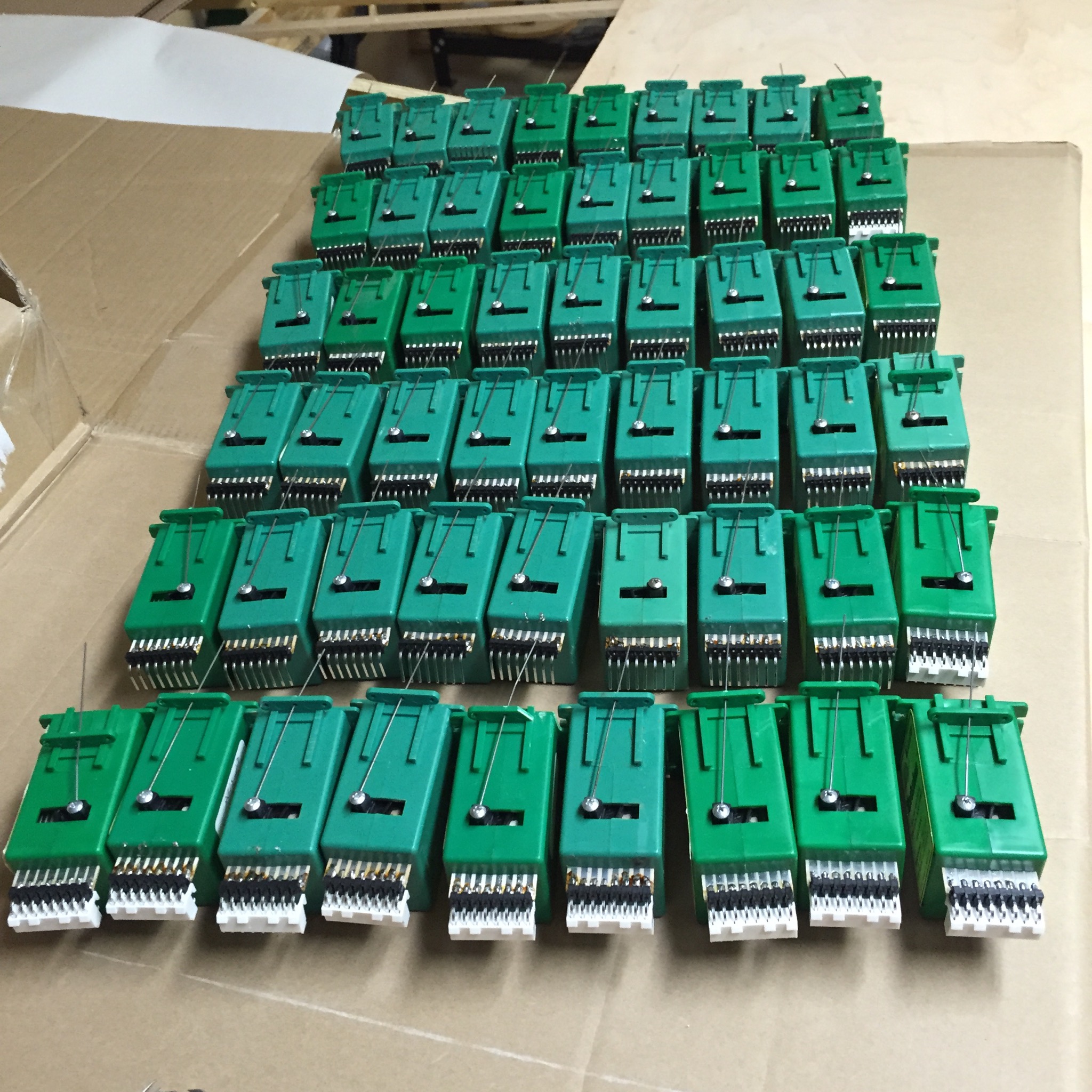
I’ve been cleaning up the boxful of used Tortoises that I got at the last State Fair flea market.   I’ve removed the wires from each one, cleaned up the contacts, and soldered on a header block.  It’s my green frog version of the Terra Cotta Army.

Header Block

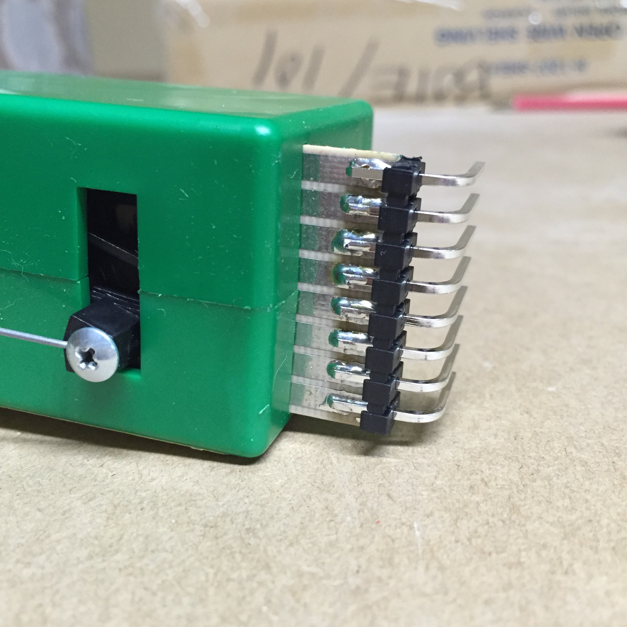
These headers are .156″ spacing right angle headers, which are designed to work with Molex connectors.  They work well enough on the Tortoise — whoever designed the board at Circuitron made something that almost, but not quite, works correctly with standard connectors.

IMG_0236.JPG

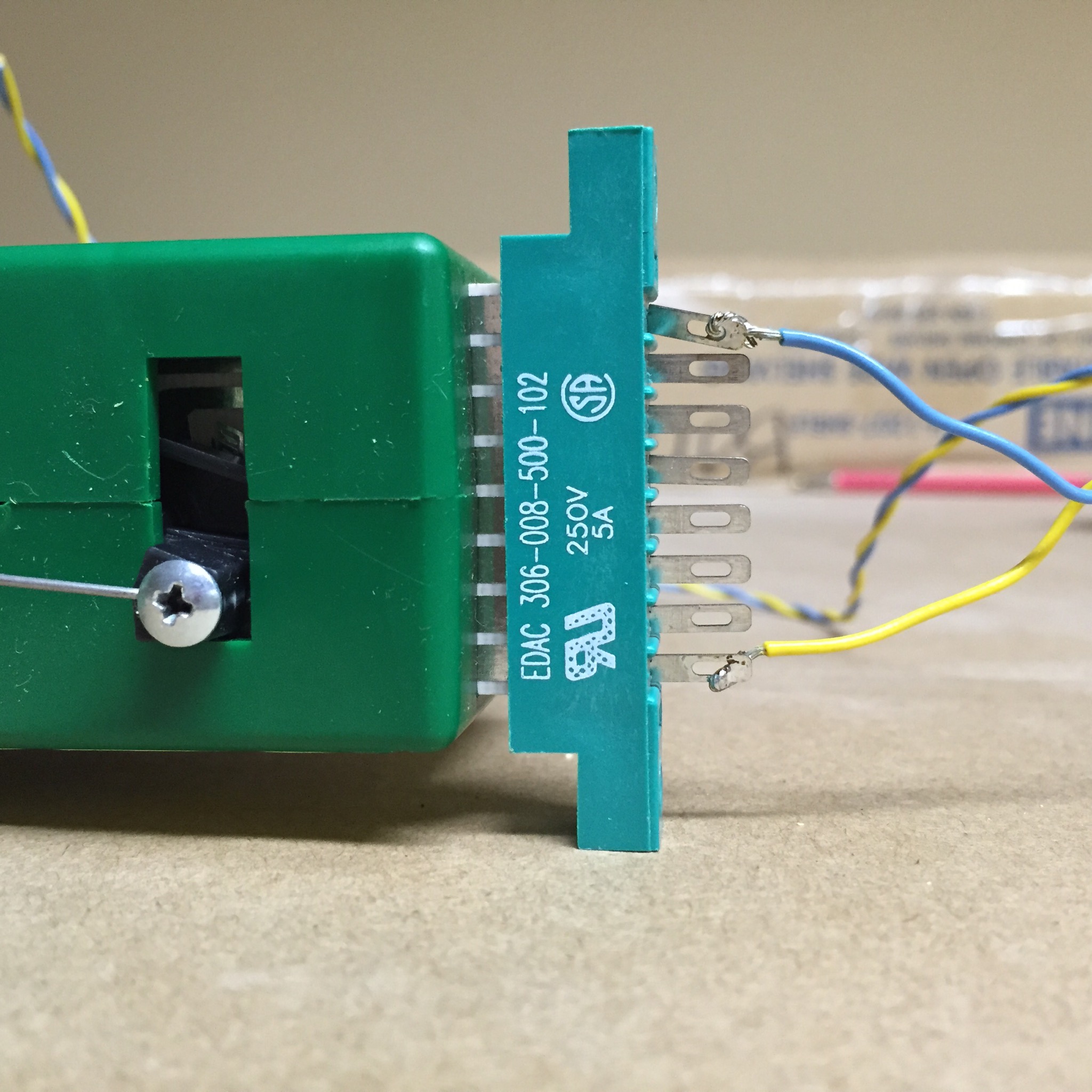
I used to use the EDAC connector plugs (available from Greenway), but these are $7 or so apiece, and they only mostly work.   They can be installed off by half a pin or so, which causes them to not work reliably.  They also can slip off due to vibration, since the board on the Tortoise isn’t the same thickness as the plug expects.

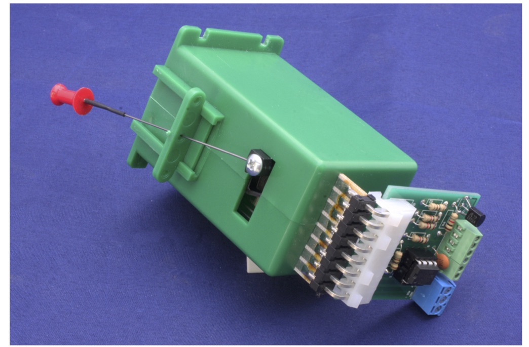
I’m going to use the RSMC (Remote Stall Motor Controller) board, which will take a logic hi/lo signal (such as from the Arduino, or a single pole single throw toggle/pushbutton) and swap the polarity on the 12V power to the tortoise.     These board have the matching connector to the headers I just soldered to all of these Tortii.

RSMC Image
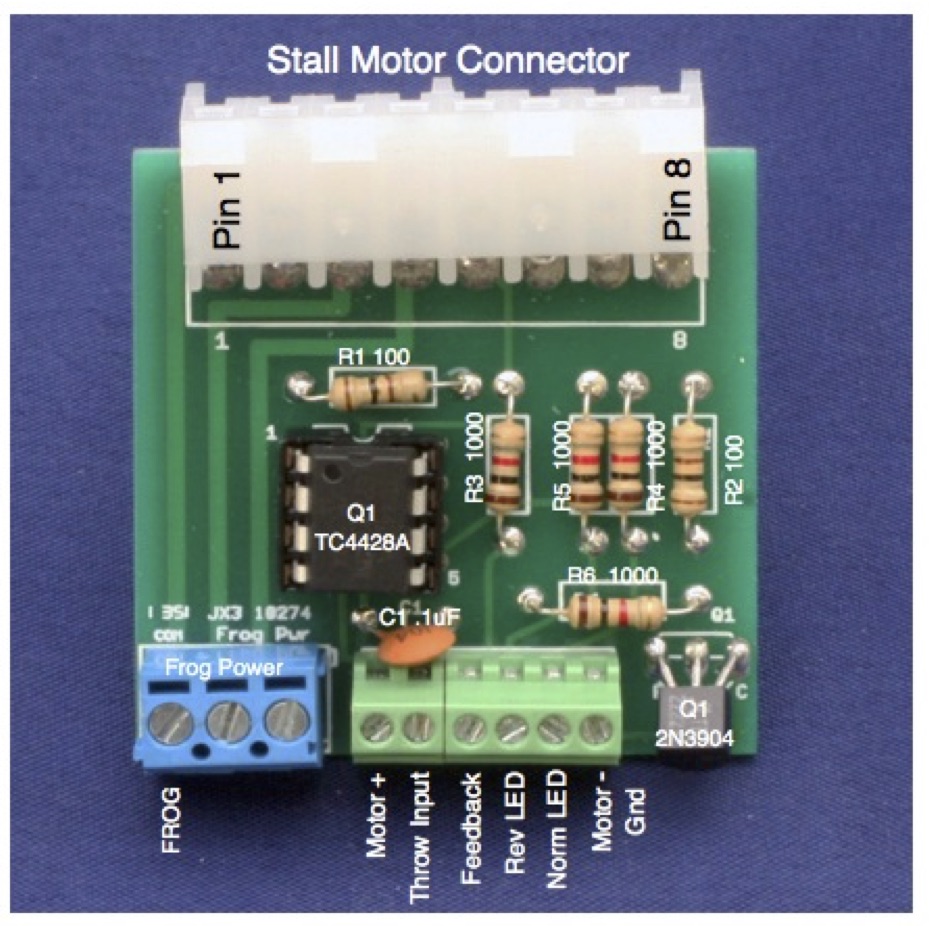
I also can wire up the rail power to the RSMC, and I’ll get the correct frog power based on the switch position.  There are additional connectors that I can use for LED indicators on the fascia.

RSMC Installed

I have all the parts for the RSMC boards on my bench, except for the PC board.  I’ve ordered them from Seeed Studio in China, and they’re somewhere on the way between Shenzhen and here.   The total cost of the board, the components, and the connectors will be about $5 each, which certainly compares favorably to anything which uses the EDAC connector.

There’s a different edge connector available in the last few years:

tte-tortconn-2477-01

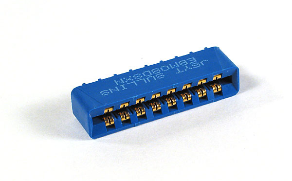
This one fits a little better, but not so much that it really is much better.  It does have the advantage of being easier to use on a circuit board (the Hare, of which I have one for testing, uses this connector).  It’s also a little bit cheaper (about $3 each).

But nothing beats the solid connection you get from the Molex connectors.  Combined with screw terminals for the other connections, I like how the RSMC is fairly easy to replace if necessary, and I don’t think they’d slip off in a Richter 8 earthquake (something my friends in California might worry about, but I don’t here in Minnesota.  Thank goodness for that.)

Maybe I should get started on laying track, so I have someplace to use these sometime soon.

DCC on a Board

I didn’t have a good box for this, or else it would be DCC-in-a-box.

All of my interesting DCC bits are tied together in one place.

DCC-on-a-Board

This board has three “upstream” connections: 2 x 120V AC (from the power supply brick and the terminal server) and one wired Ethernet (not shown).

Downstream (towards the layout) are connections for:

  • LocoNet (throttle bus)
  • Digitrax Simplex wireless throttle support
  • Rail A, B (DCC input to the circuit breakers that feed the power districts)
  • Programming A,B (with the Programming Track Booster in place)
  • Serial ports (via the terminal server) to the LocoBuffer and to the CMRI bus that will go throughout the layout.

The configuration shown here (except for the CMRI connection) has been built, tested and used for various locomotive projects while I was between layouts.   This makes the wiring of the layout a bit simpler and also makes it easier for me to trust that the basic DCC wiring configuration is good, and that any problems I encounter as I lay track and wire it up is due to the new work and not these components.

Electronics Shelf

I’ve put in a shelf to hold the DCC board.  I’ll have a separate switched circuit under the layout to be able to turn the layout on or off from a single point.   This switch will have a light easily visible from the main room entrance, making it hard to miss if I turn out the room lights and have left the layout on.

If you happen to care, download the DCC on a Board image as a PDF file: DCC on a Board

Power to the People

My bench work is a U shape, with the two uprights set in from the outer walls of the basement (since layout edge is more important to me than running length). The big downside to this is that the inner portion of the layout now has no convenient access to power outlets.

Today’s project was electrical. Run some 120V power to outlets on the inside of the U. A side bonus – one of those outlets has a pair of USB charging points. That will keep my streaming tunes (and news) running.

Overall, a simple project. But the payoff will continue for a very long time.

Next will be the switch (with pilot light) for the RR electronics.

IMG_4725.JPG

IMG_4717.JPG

I find that I use my laptop a lot when programming locomotives. So I put in a laptop drawer right next to where the roundhouse goes. Now I will be able to set up the laptop anytime I need it. This drawer will have the Locobuffer’s USB cable attached, so everything I need for programming will be right here.

IMG_4719.JPG

IMG_4721.JPG

Benchwork!

The base framework is in place. Standard L-girder, made from plywood dimensional lumber. Just about everything is salvage from previous layouts.  Sitting on top is sheet cardboard – to provide a semi-solid base for track planning doodling.

I do not do the CAD track plan thing. I just don’t find it easy to sketch in those programs. So I will use track templates (turnouts, cross-overs, etc.) and some sweep-sticks for radius measurements. I can also use several building mock ups to help figure out how the urban scenery can work. Reaching over a wheat field is very different than reaching through an alley.  You can’t really get a feel for that in a CAD design.

IMG_4677.JPG

IMG_4681.JPG