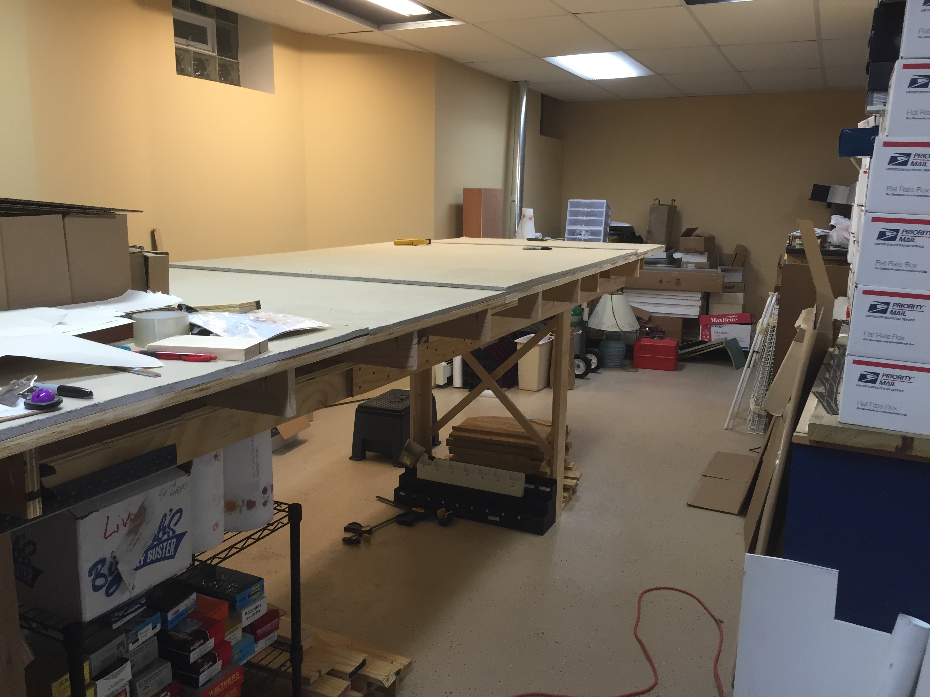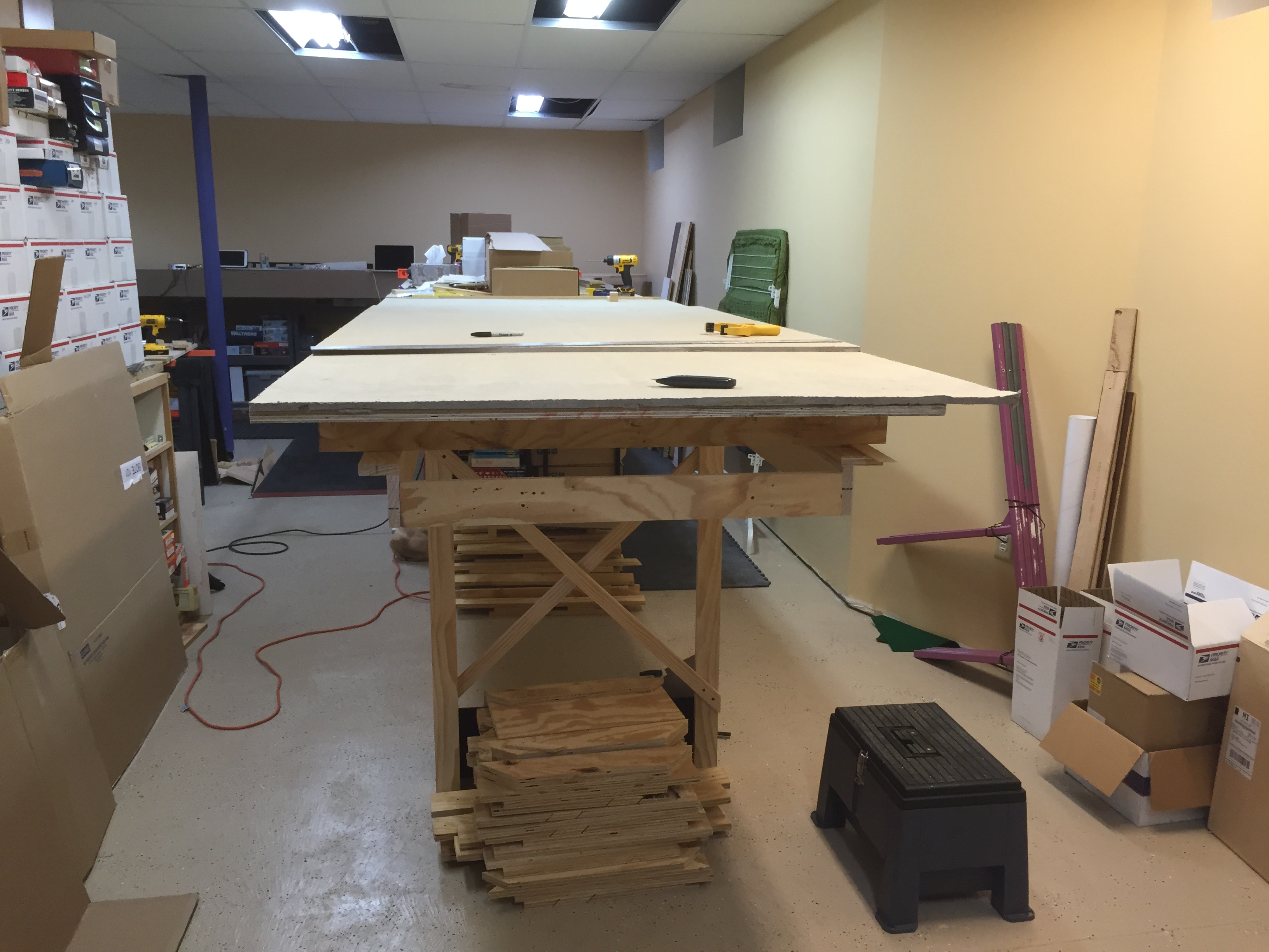
So much has been done in the last several months. From bare benchwork to an operating switching district, this portion of the layout has been the focus of my modeling time for a while now, and it’s coming to a good place.
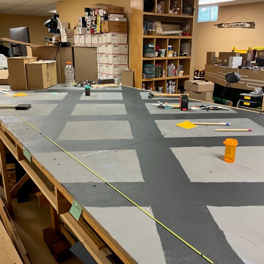
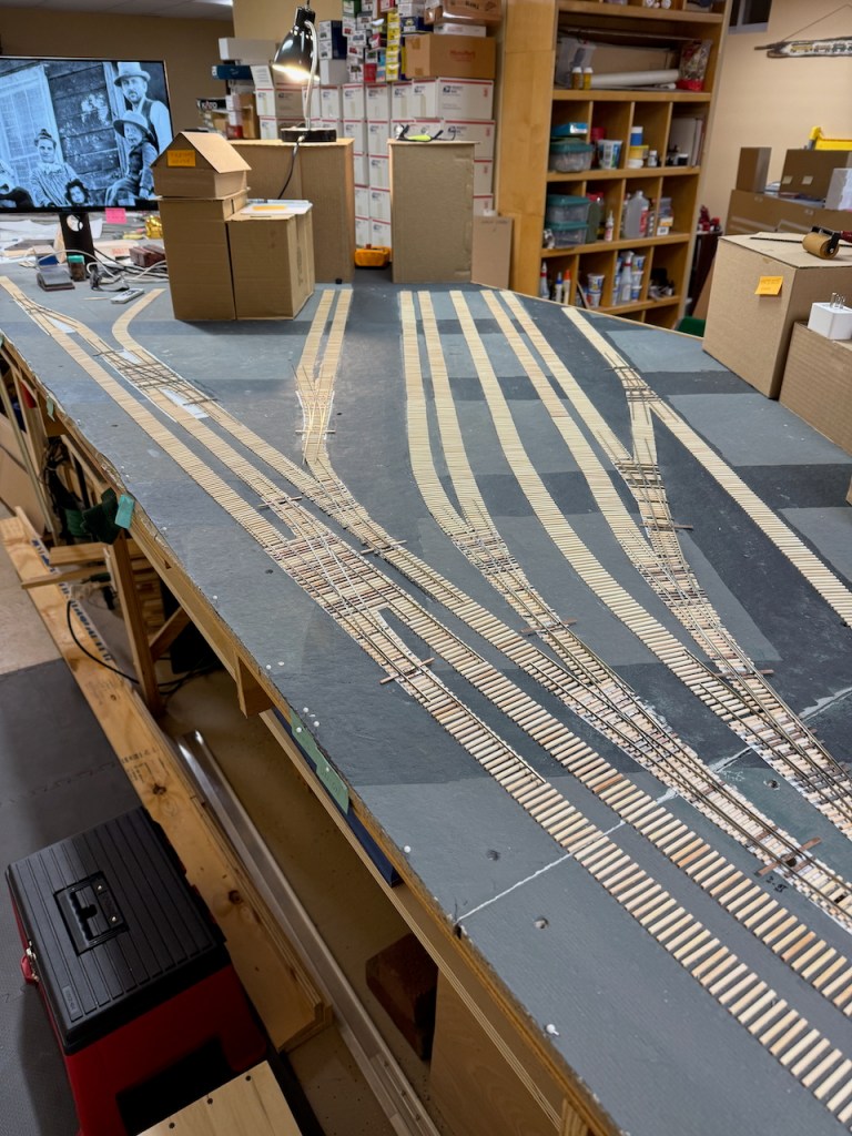
A street grid has been laid out. The front edge of the benchwork along the aisle is The Embarcadero, and the streets running away from the camera are Drumm and Front, ranging from Pacific to Greenwich. All more or less just to the east of and below Telegraph Hill.

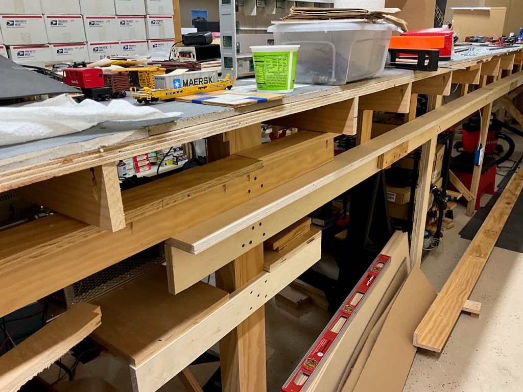
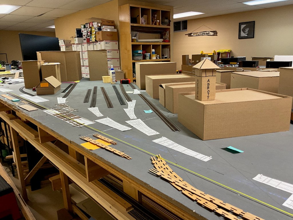
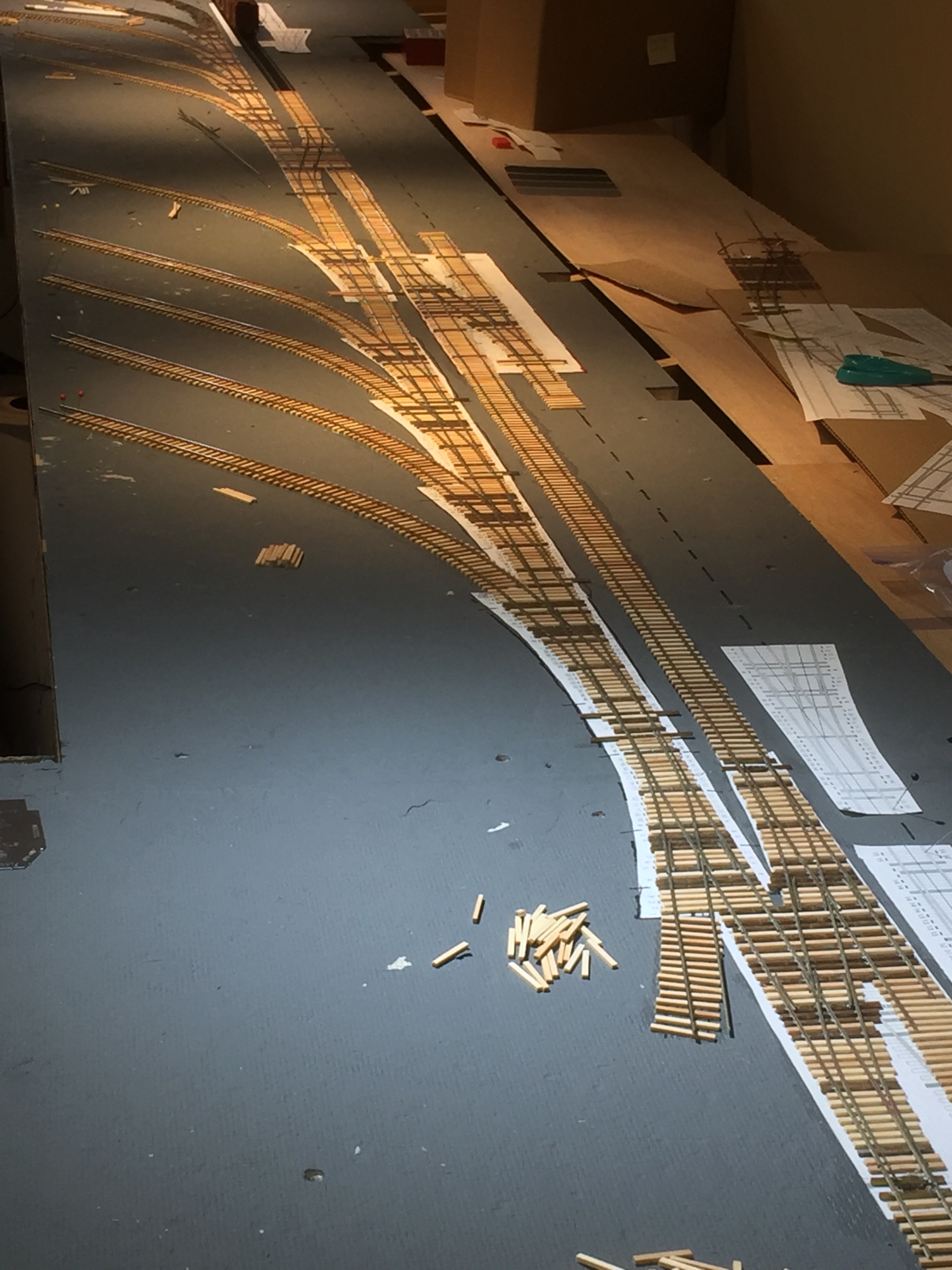
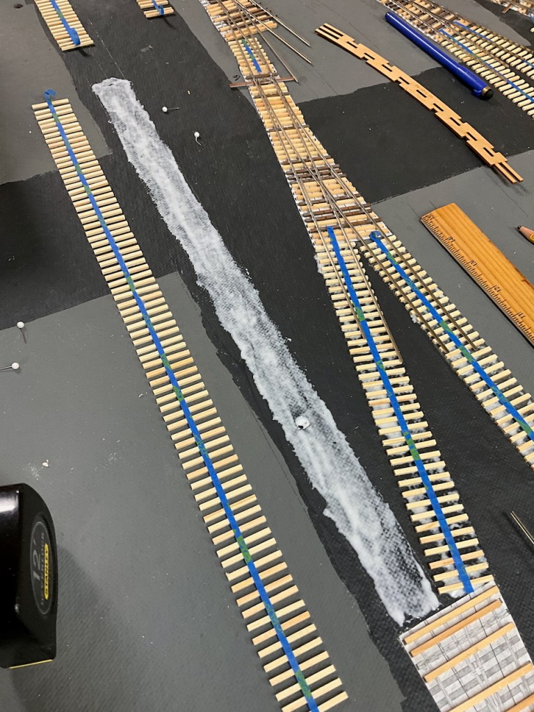
This panoramic shot shows all of the ties laid down, now that I’ve got that underlying painted street grid. Switch templates are glued down to the homasote, then ties glued atop that template, and then long strips of ties connecting them all. These long tracks extending several blocks back are definitely the longest stretches of “straight track” on the whole railroad.
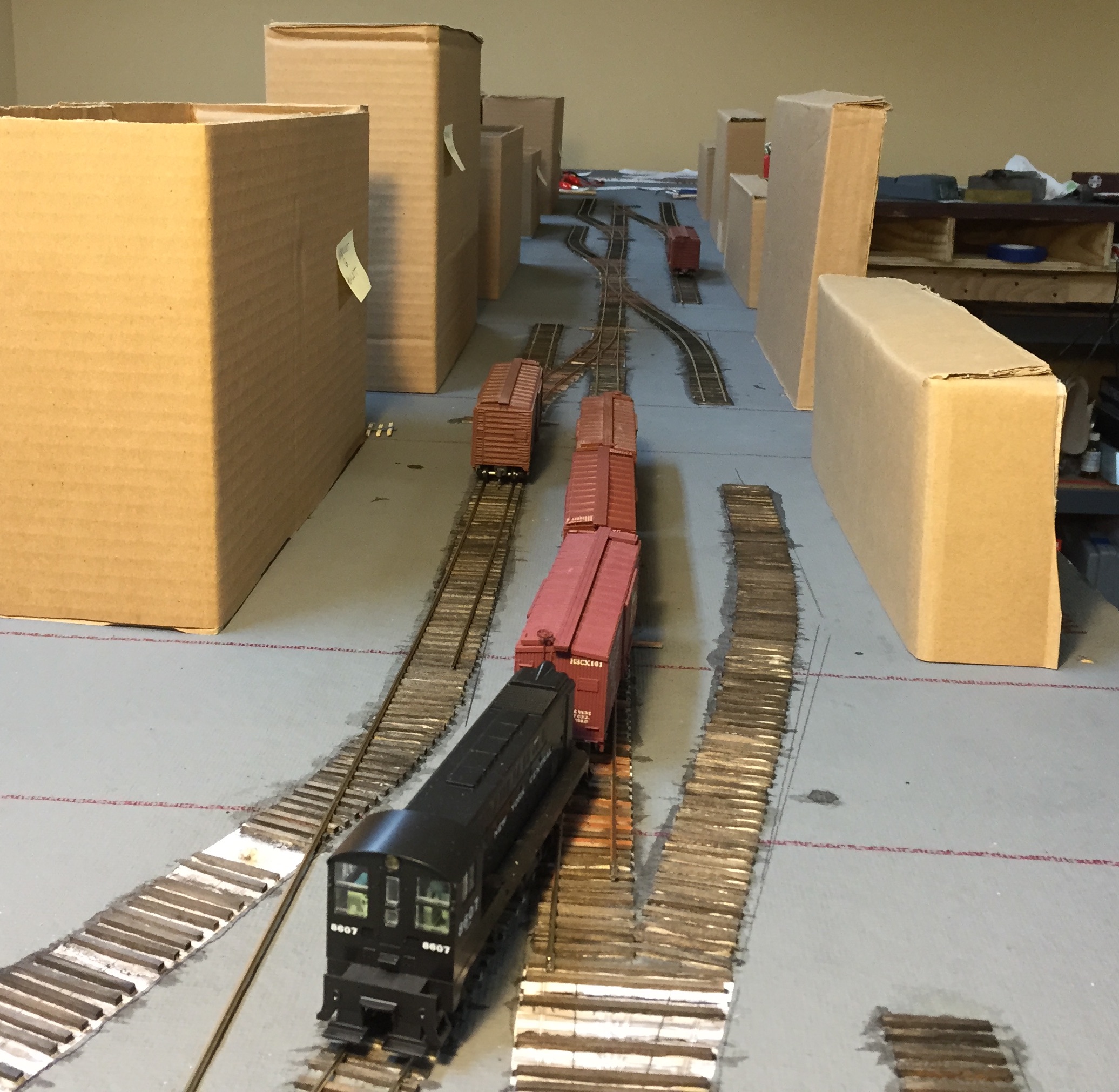
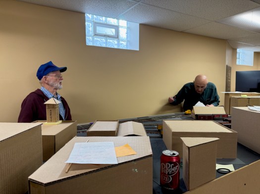
Note the building mockups in place for much of this. I built these to get a feel for sight lines, and how far people can reach around or between them (not very!). Simple cardboard rectangles with a roof glued on top – nothing fancy, but differing height and vaguely differing roof lines. I could make several of these a night, and without a doubt that was time well spent. Further south, towards Market St, these buildings get pretty tall (it is downtown, after all) and provide a nice separation between this Produce District and the “South of Market” area (that is yet to be built).
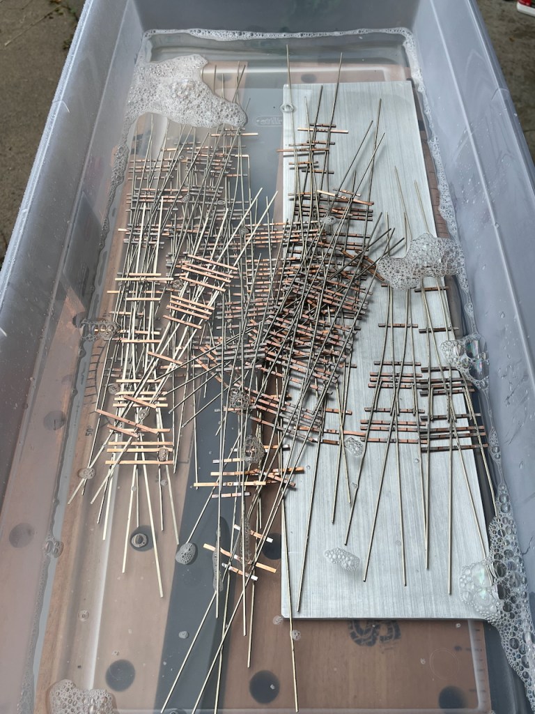
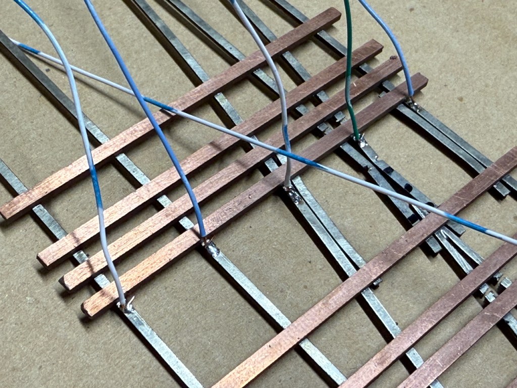
Many, many switches were built. It’s around 23, with several being crossovers. One or two a night for a couple of weeks, and then time to prepare them for installation. Proper cleaning, and then soldering drop leads. Every frog gets a wire, then a minimum of two wires (one for each “primary” rail, and on crossovers even more). “Bay Side is BLUE” is the mnemonic (track power bus wires are blue and white).
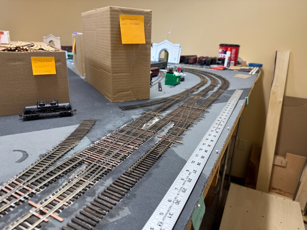
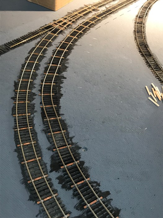
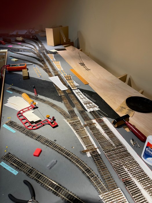
Then it’s time to lay all of the rail. Starting at the tracks along the aisle, I finished up the curves from the other portion of the layout, and then did each of the three “main” lines. Once those were all complete, down to Market St, it was time to extend the spurs inland. Many spikes were inserted (more than a few making the ultimate sacrifice — I’ve done a lot of hand laid track by now, and I don’t think I’d call myself good at it yet). Lots of gauge checking.
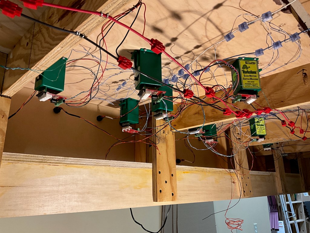
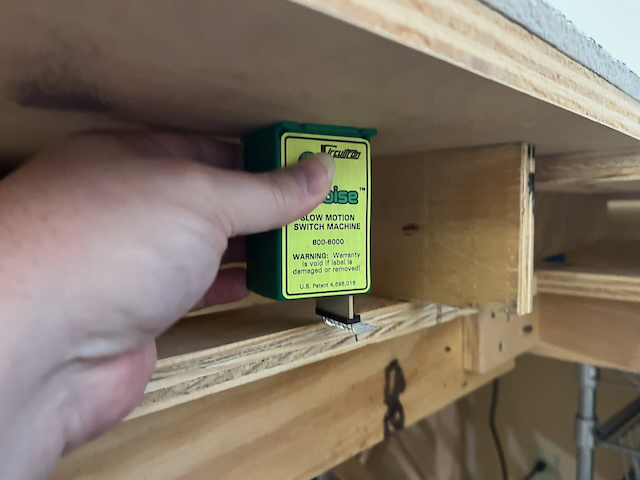
Then it’s time to install switch machines. Lots of them. This is why I lowered the L-girder: to make short order of this for those turnouts that are right above the girder (and that’s several of them). Alas, I appear to have not taken any pictures of the spaces with the Tortoises before the wiring began.
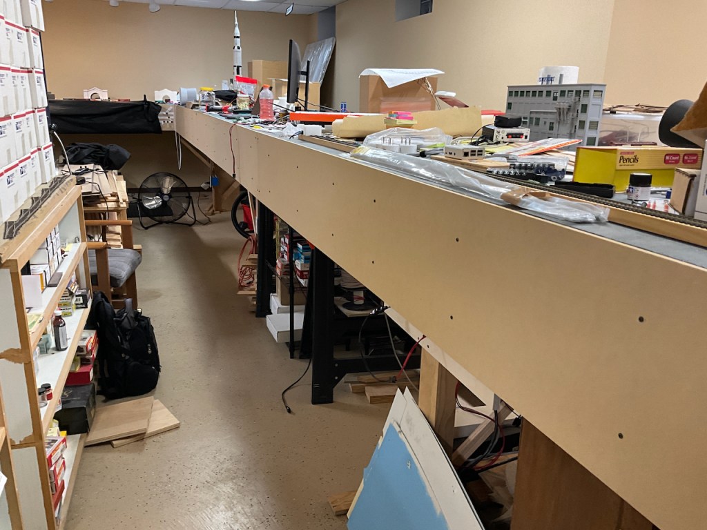
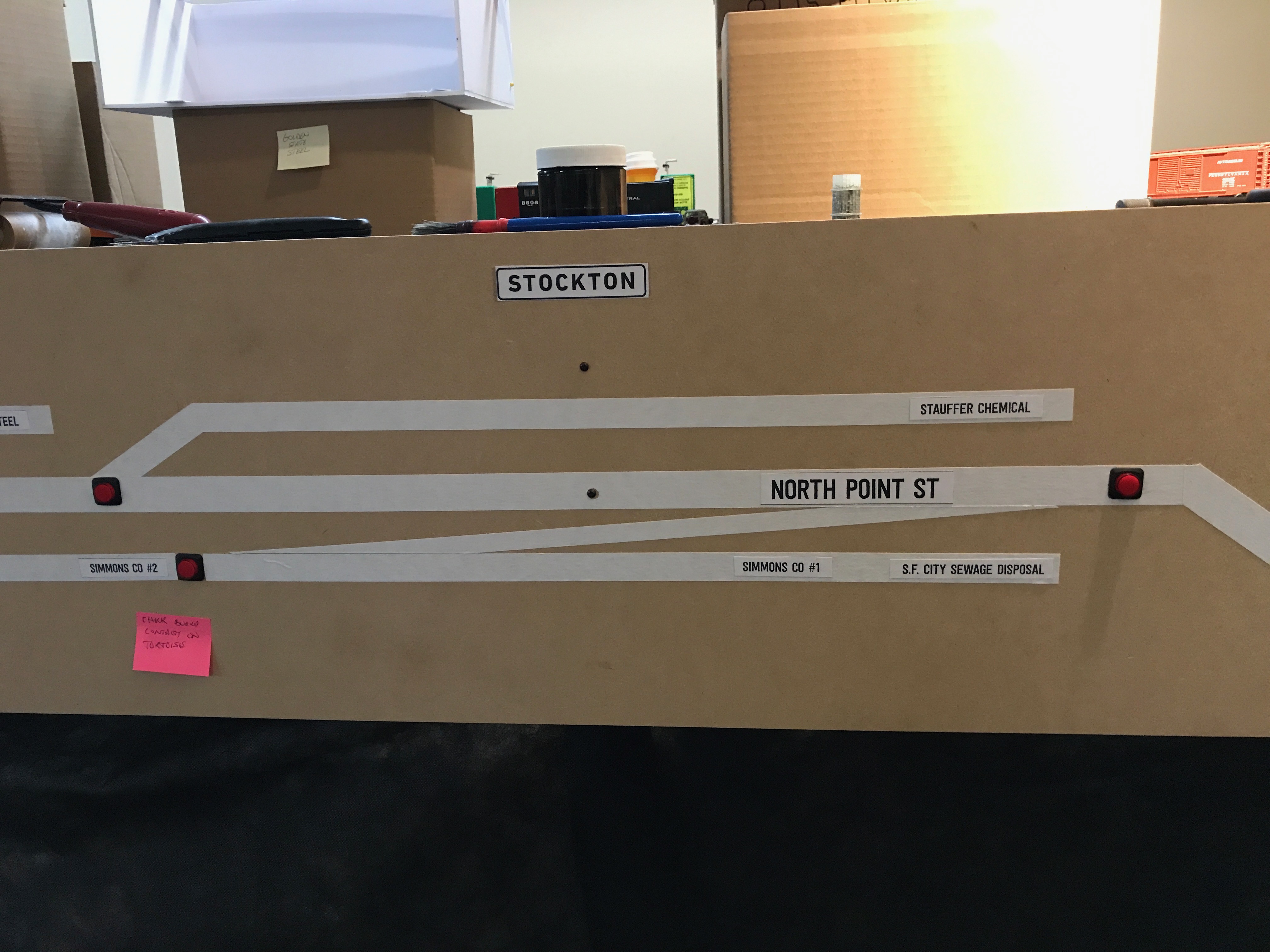
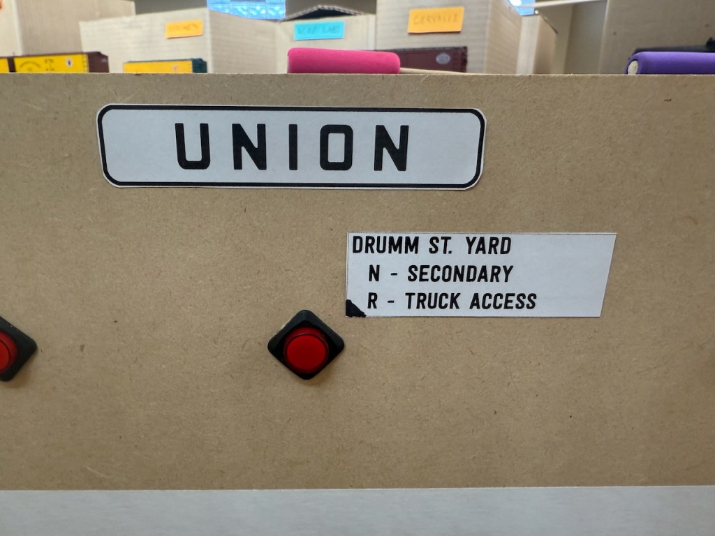
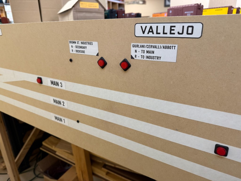
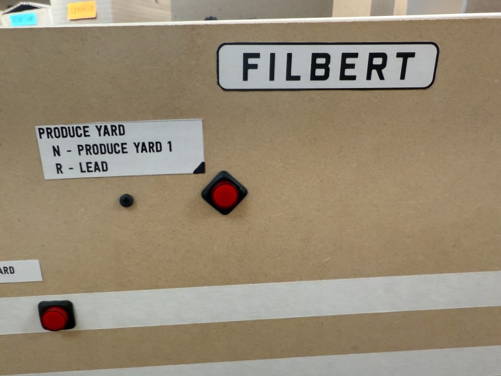
Once those were installed, it was time to put up the fascia. 1/4″ MDF, 12″ high and then cut to length. Holes drilled for the switch controls and “main” tracks indicated with tape. In other portions of the railroad, all of the other switches for spurs were able to have the same tape treatment, but that didn’t work on this section due to the sheer amount (and length) of those tracks heading away from the mains. This led me to just label each button and hope that crews can figure it out. Every switch control is straight out from the points of the associated switch. There are three groups of tracks here (Drumm St. Industries, Drumm St Yard and the Produce Yard). Each label has the grouping name (e.g., Produce Yard), and then some indication for what each of Normal and Reverse would be (e.g., Track 3 or Lead).
Oh, and all of the streets that cross the mains get street signs, using a very nice replica font for this (Fog City Gothic). Since town names don’t really do anyone any good (it’s all San Francisco), I had to find something with finer granularity to help locate things.
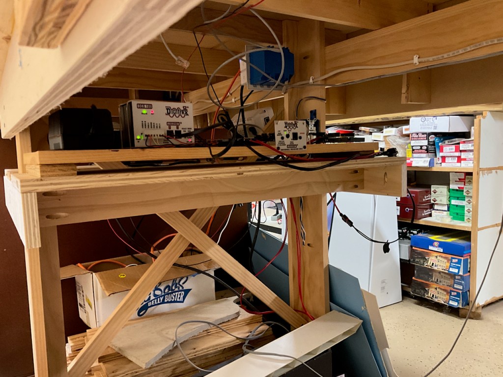
Then many evenings under the layout putting it all into operating shape as far as the electrons go. Power to each Tortoise control board, wires to the pushbuttons that are the operator control for each switch (latching on-off pushbuttons with built in LEDs), frog wires to the same control board which uses the Tortoise contacts to properly switch between blue & white track power feeds, and then additional track power drops.
I am a big fan of the suitcase connectors (3M 905 for 14ga to 20ga connections, and Corning UB2A for connecting the 24ga drops to a 20ga local bus extension). And please do get the correct crimping tool, especially for the UB2A. I’ve done many of them using a regular channel lock pliers, and they’re *SO* much easier to do with the right tool.

I could then move the quick-n-dirty staging tracks to south of Market, representing the SP King Street interchange and the various State Belt industries that will be in this area. Right now, it’s just two tracks (commercial turnouts & flex track, since it gets moved from time to time).
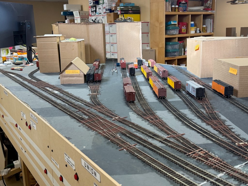
It was time then to dig out some more freight cars from storage (many of these had not seen the light of day since 2012 and the dismantling of the St. Paul Bridge & Terminal). Quick checks of wheel gauge and coupler height were performed (with only a couple of fixes needed). The road name mix is a bit off of what I would expect to see, but that can be remedied over time (for example, there are more NP reefers in my fleet than I would expect to see in SF).
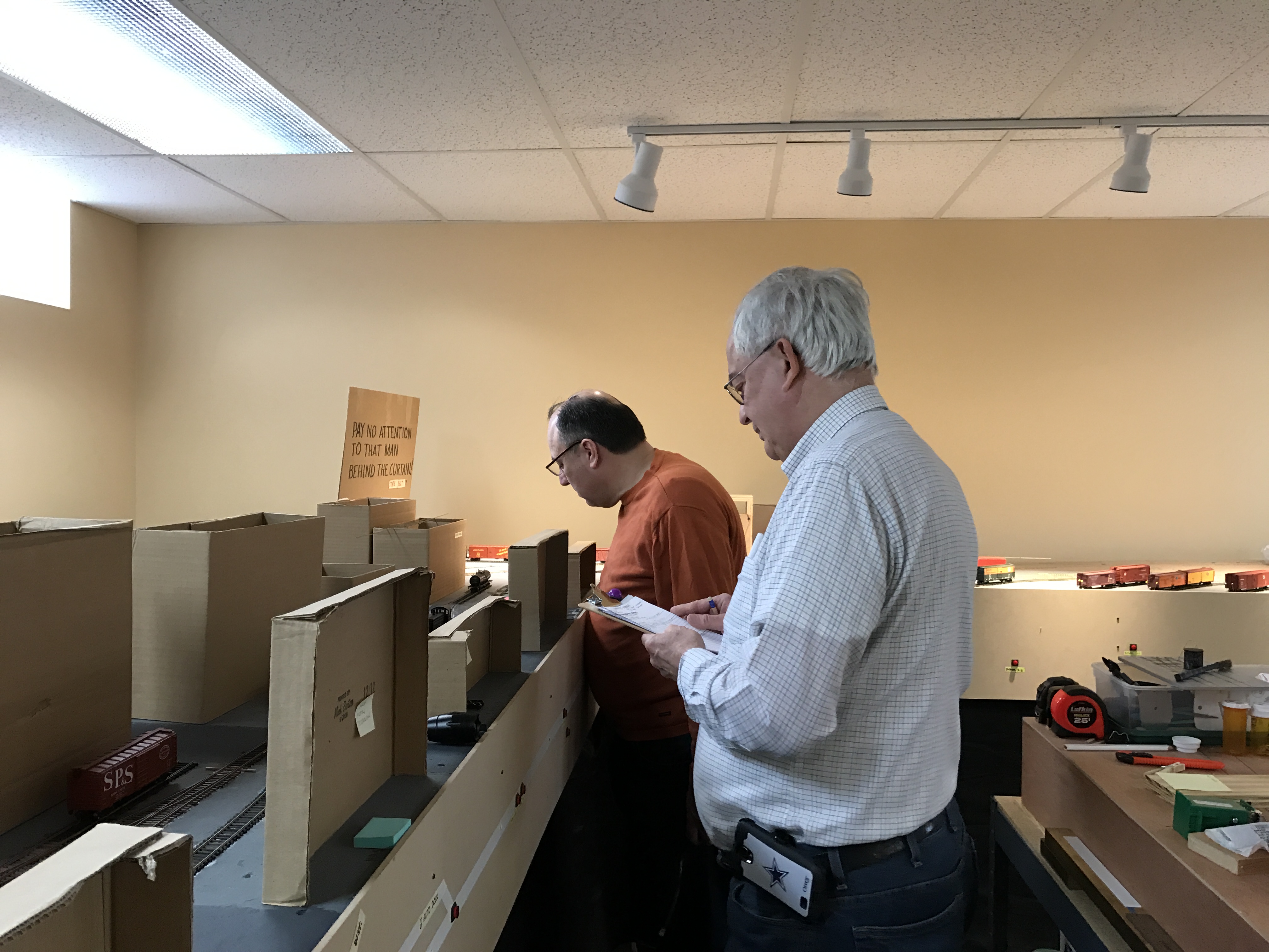
Then it was time for a break-in run of the new Produce District. On January 20, 2025, an illustrious (notorious?) crew came and ran for a couple of hours, moving some cars around per their B-7 instructions. A couple of small issues were identified, but no major concerns were found and I think they had a good time.