I didn’t have a good box for this, or else it would be DCC-in-a-box.
All of my interesting DCC bits are tied together in one place.
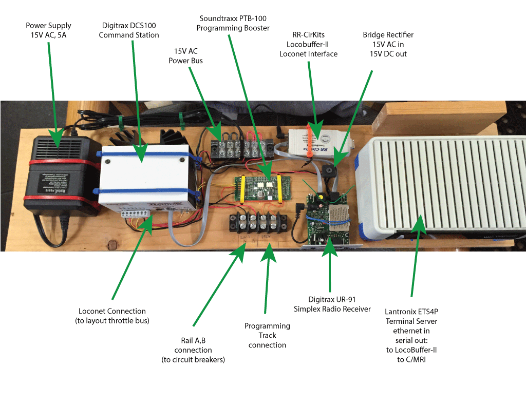
This board has three “upstream” connections: 2 x 120V AC (from the power supply brick and the terminal server) and one wired Ethernet (not shown).
Downstream (towards the layout) are connections for:
- LocoNet (throttle bus)
- Digitrax Simplex wireless throttle support
- Rail A, B (DCC input to the circuit breakers that feed the power districts)
- Programming A,B (with the Programming Track Booster in place)
- Serial ports (via the terminal server) to the LocoBuffer and to the CMRI bus that will go throughout the layout.
The configuration shown here (except for the CMRI connection) has been built, tested and used for various locomotive projects while I was between layouts. This makes the wiring of the layout a bit simpler and also makes it easier for me to trust that the basic DCC wiring configuration is good, and that any problems I encounter as I lay track and wire it up is due to the new work and not these components.
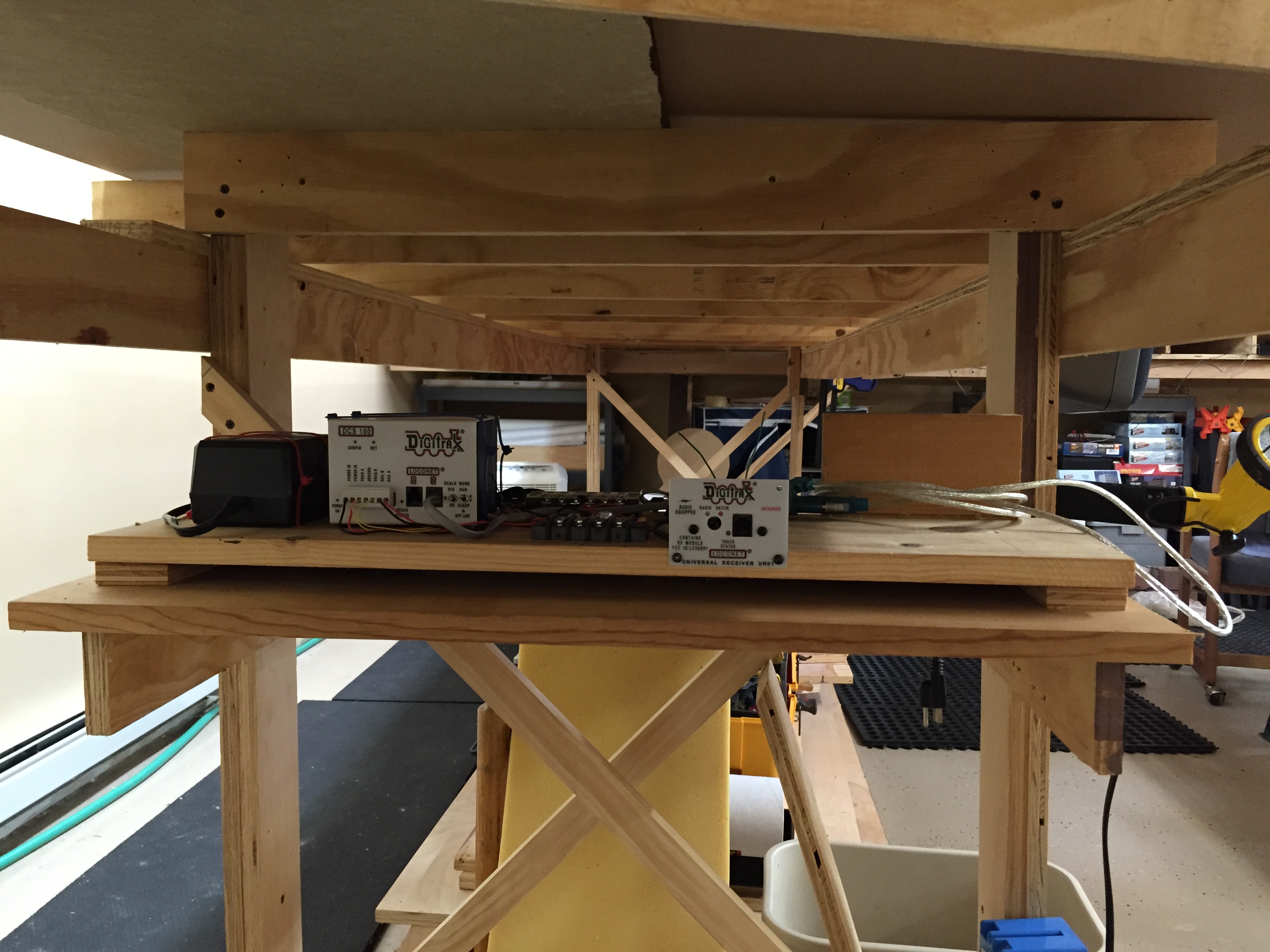
I’ve put in a shelf to hold the DCC board. I’ll have a separate switched circuit under the layout to be able to turn the layout on or off from a single point. This switch will have a light easily visible from the main room entrance, making it hard to miss if I turn out the room lights and have left the layout on.
If you happen to care, download the DCC on a Board image as a PDF file: DCC on a Board
